It must be pointed out that although the focus of this article is about Dinky Toy development, the order of the steps outlined below would be applied to all in house manufactured products, though not all steps would be relevant (e.g. new parts for Meccano outfits). The use of the word “prototype” denotes the actual real life vehicle, not the model. The accompanying illustrations follow the development of DT 199, the Austin Seven Countryman introduced in May 1961.
A well proven route
Product development followed a well proven route:
1) The New Product Committee would identify a proposed model to manufacture.
2) The committee’s choice would be passed to the New Product Development Manager who would liaise with the manufacturer (e.g. Ford Motor UK) and obtain photographs and drawings. In the absence of good photographs of all sides of the prototype, a trip would be taken to photograph the prototype further using a wooden measuring bar graduated in inches and placed against the prototype as required. By signing confidentiality agreements with manufacturers, details could be obtained of vehicles that were yet to reach the public domain. This way a Dinky would be released to coincide with the maker’s launch.
3) Using the above data, a draughtsman assigned to the New Products Manager would prepare an assembly drawing of the Dinky showing the proposed number of parts, materials and color scheme. The scale of the assembly drawing would be 1:1 so as to give the correct impression of size.
4) Next to the Drawing Office, a small Model Shop would manufacture a working model at the proposed scale, especially if a mechanism needed to be proven. Not all proposed products would need a model if they were part of an established and proven Dinky group (e.g. saloon cars). Models would be made from a variety of materials such as wood, brass, plastic, sheet steel, or a combination as required.
5) Using the assembly drawing and historical data from previous similar products, the Costing Department would prepare a rough estimate of manufacturing and packaging costs. With this information and the model shop mock-up, the New Products Committee would make a final decision on whether or not to proceed with development.
6) The Drawing Office would now proceed with a detail design of all the new parts required.

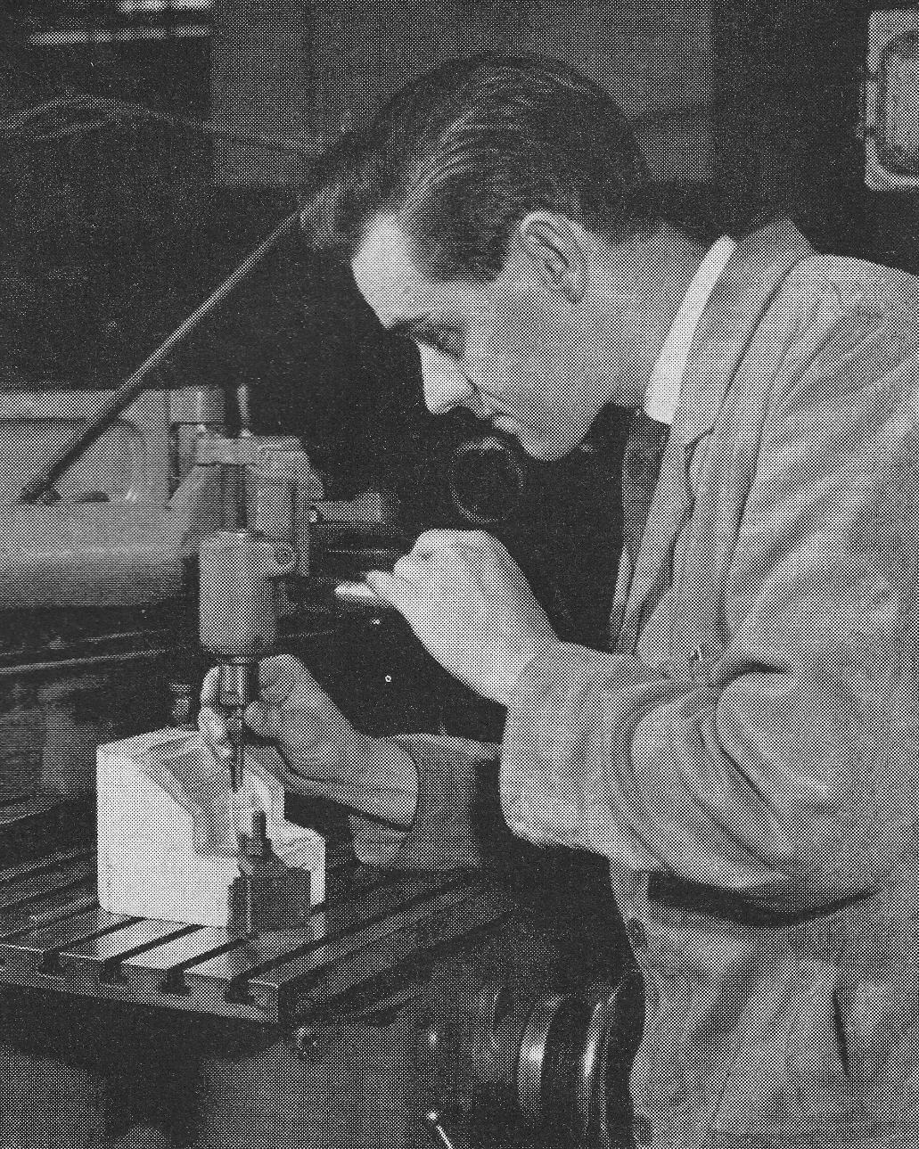
A discussion on the Austin Seven Countryman in the Drawing Office at the Binns Road factory of Meccano Limited.
Image: Meccano Magazine
7) As soon as detailed parts became available for checking, a Tool Designer would study each part and determine where the tooling split lines (parting lines) would be. This was a skilled job with the aim to make the split lines as unobtrusive as possible consistent with ease of manufacture. Tool design and pattern manufacture could now commence.
Patterns would be carved in wood at 3 or 4 times the intended size of the finished model. The pattern is “male”. “Female” casts are now taken from the pattern in wear resistant resin whose boundaries follow the split lines already determined. These casts are used by the toolmaker on die sinking machines (pantograph copiers) to create the moving parts of the tool in steel.

A pattern maker at Binns Road prepares a wooden model of the new vehicle.
Image: Meccano Magazine
Some further comments about patterns:
Meccano did have an in house pattern shop, but capacity problems lead to the use of external pattern makers in late 1960’s. The quality and accuracy of these pattern makers provided an opportunity to reduce the number of dimensions on detail drawings. Provided the drawing was drawn accurately at 3 or 4 times finished scale, the pattern maker would take their measurements directly from the drawing and with the aid of a good set of photographs create the pattern. Obviously, areas of designs that related to correct fit and function of working parts (e.g. doors, etc.) would still be dimensioned, but not the 3D shape and profiles of the external bodywork.
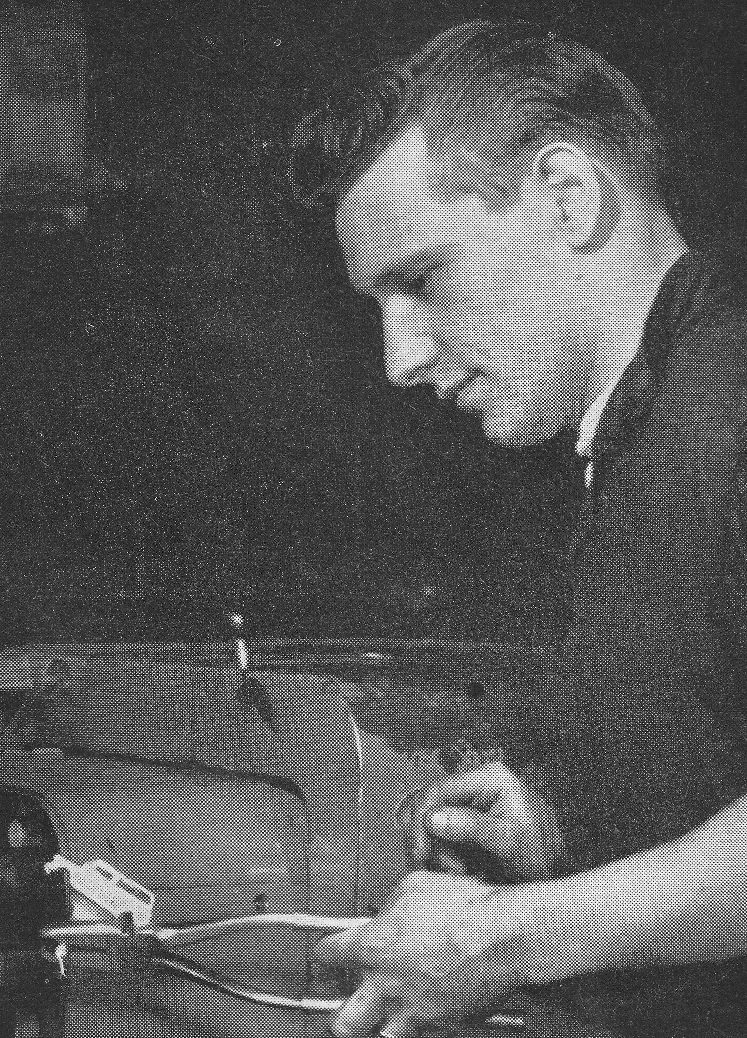
A pantograph in action, with the 3D cast on the right and the workpiece on the left.
Image: Meccano Magazine
Not all parts required a 3D wooden pattern. In the case of parts with an irregular profile but a fixed depth, one or more steel templates would be used on the pantograph (die sinking machine).
A toolmaker at work on a pantograph machine.
Image: Meccano Magazine
It’s now necessary to describe the manufacture of the clear polystyrene windows fitted to many models which fit inside body castings with a minimum gap. To achieve this, a duplicate steel core is made, identical to the one in the diecast tool for the body. After hardening, this core is sent to a special manufacturer and used as a “hobb”. The hobb is forced under extreme pressure into a billet of special steel, thus creating the cavity of the window. Several machining operations follow on the billet to make it suitable for fitting into the window injection mold.
The hobb would be used repeatedly depending upon the number of cavities (impressions) in the window mold. The special steel is capable of receiving the very high (mirror) polish necessary to mold the windows crystal clear.
8) When extra tool making capacity was required, subcontracted tool makers were used. In this case only the component designs and drawings showing the location of the split lines would be issued. The subcontractor is now responsible for tool design and pattern making. However, such tool designs and patterns had to be submitted back to Meccano Ltd for approval prior to manufacture. Meccano had a strict tooling standard for subcontractors to adhere to.
9) Finished new tools would be tried and sample parts assembled. Any modifications necessary to improve fit or function would be carried out and the tool tried again.
A fresh casting.
Image: Meccano Magazine
Diecast parts would be placed in a vibratory machine with graded hard stone media to remove flash and then “bonderised”, a liquid wash process that cleaned the castings and etched the surface so paint would adhere well to the Mazak.

Sprue and flash removal.
Image: Meccano Magazine
Painting would be carried out in automatic spray booths that transported the castings and spun them under strategically placed spray guns to apply an even coat on all surfaces. The parts would then be transported through an oven to harden the paint.
Loading the auto sprayer with body castings.
Image: Meccano Magazine
Mask spraying.
Image: Meccano Magazine
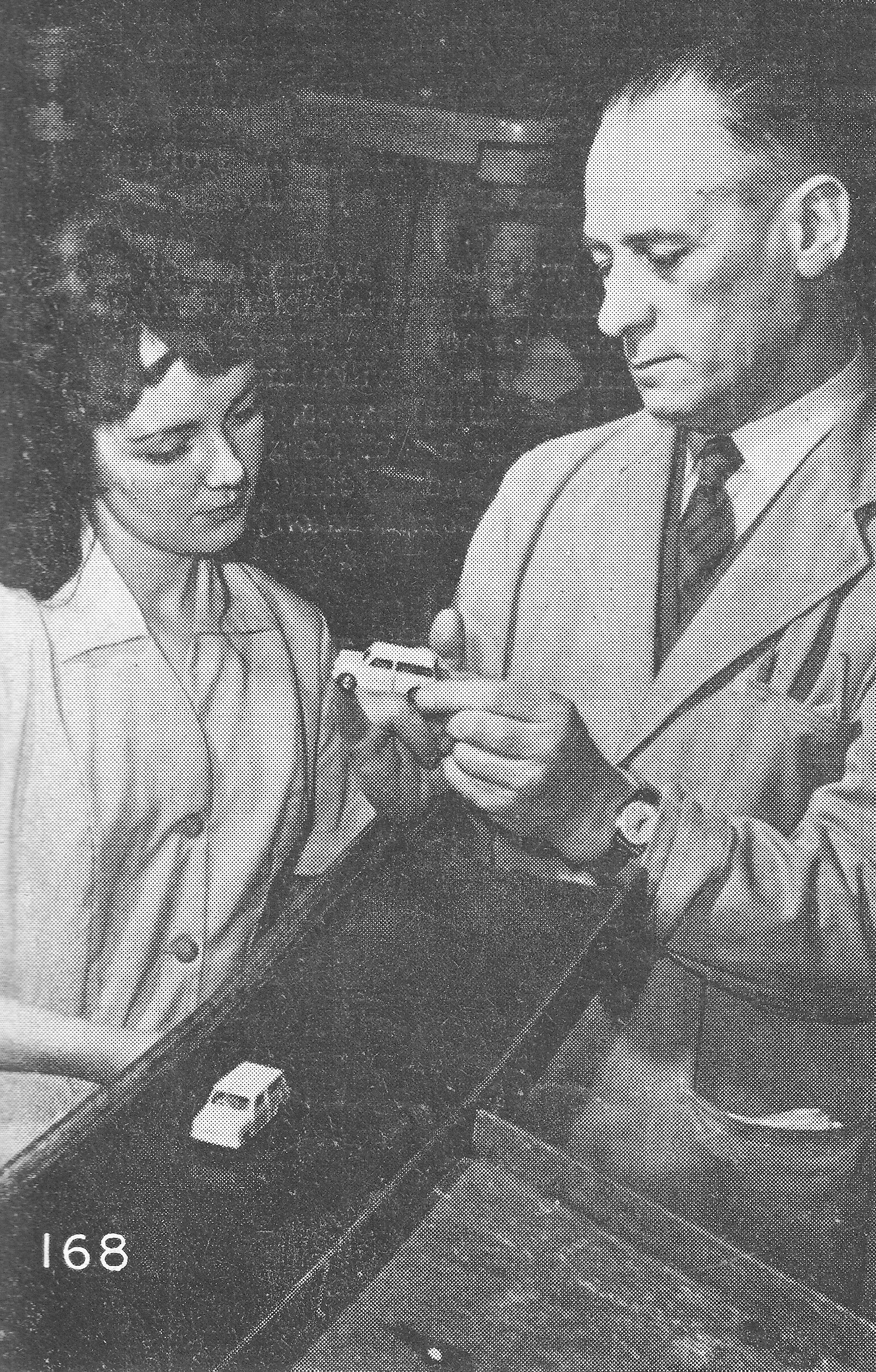
If secondary detail was required after hardening, the castings would be hand sprayed in individual booths. In the booth the part would be placed behind a mask to shield everything except the detail to be sprayed. Several color schemes may be tried to help the New Products Committee and sales staff arrive at a final decision.
The final touch up process which ensures protection of the finish of the vehicle.
Image: Meccano Magazine
10) With all tools and parts approved, a 500 sample manufacturing run would be processed from start to finished boxed product. After fixing any remaining issues, full production would commence.
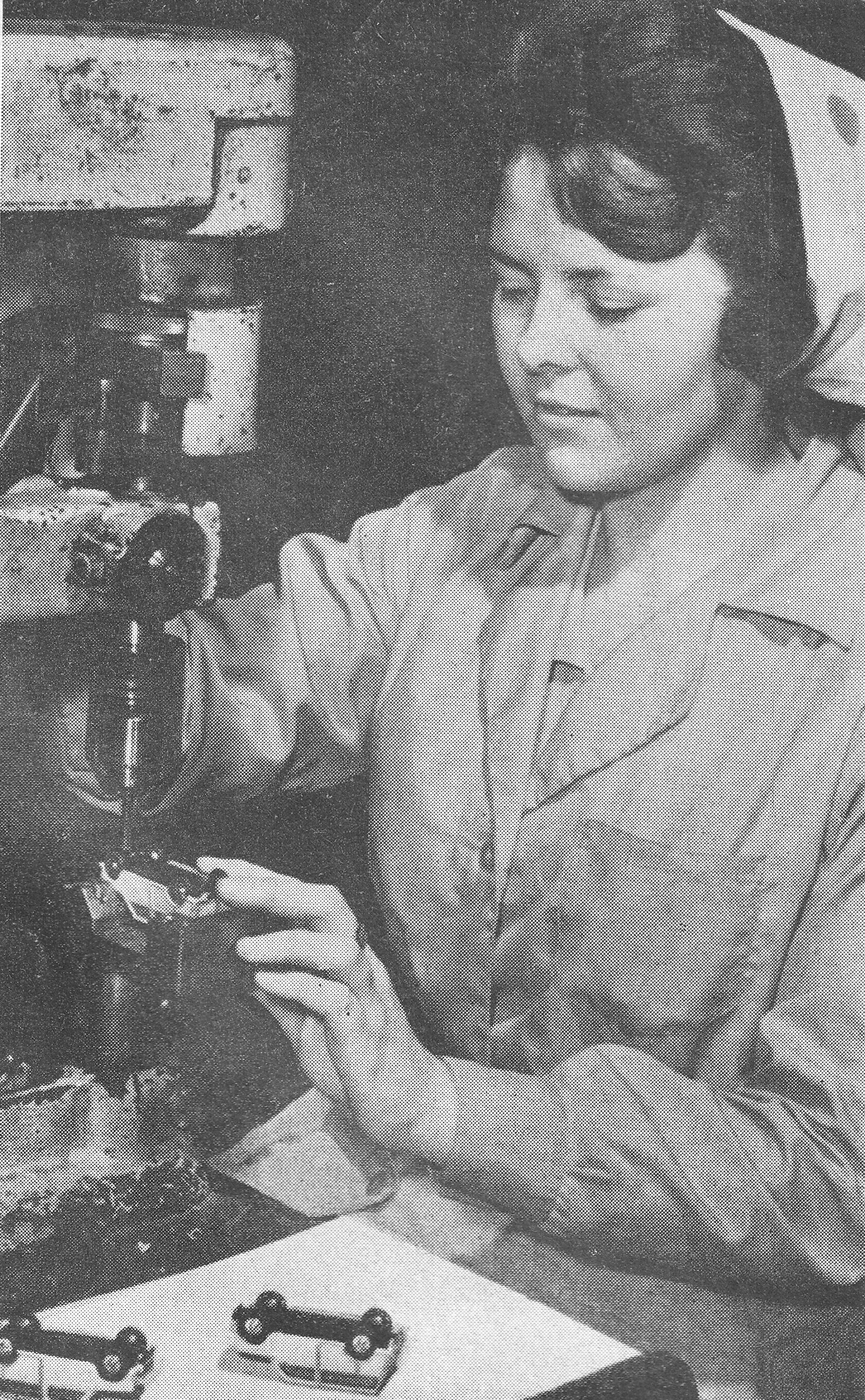
Assembly of the base and the body of the Dinky Toys model.
Image: Meccano Magazine
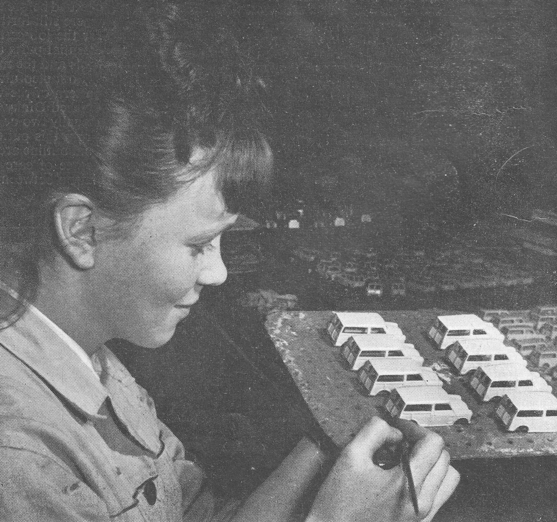
The final inspection which precedes the sample run of 500 models.
Image: Meccano Magazine
During steps 5 to 9 other areas would be getting their house in order, such as material purchasing, detail costing, packaging design, sales and marketing, paint shop masks, assembly jigs and preferred sequence of assembly. By the late 1960’s, overall time to market from idea to production was reduced to 12 months by using concurrent engineering methods. This enabled the release of two new Dinkys per month.
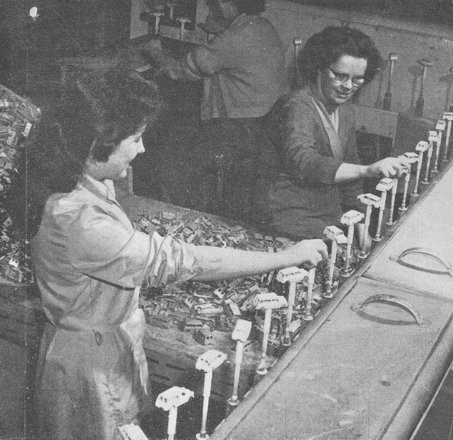
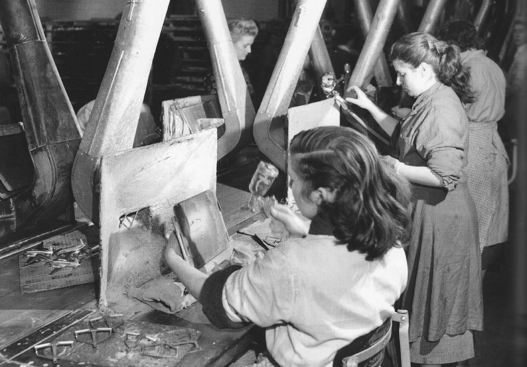
The traditional method of assembly was down a conveyor, with female operatives on each side doing a single operation from the parts provided to their work point. At the end of the conveyor, the completed model would be inspected and boxed.
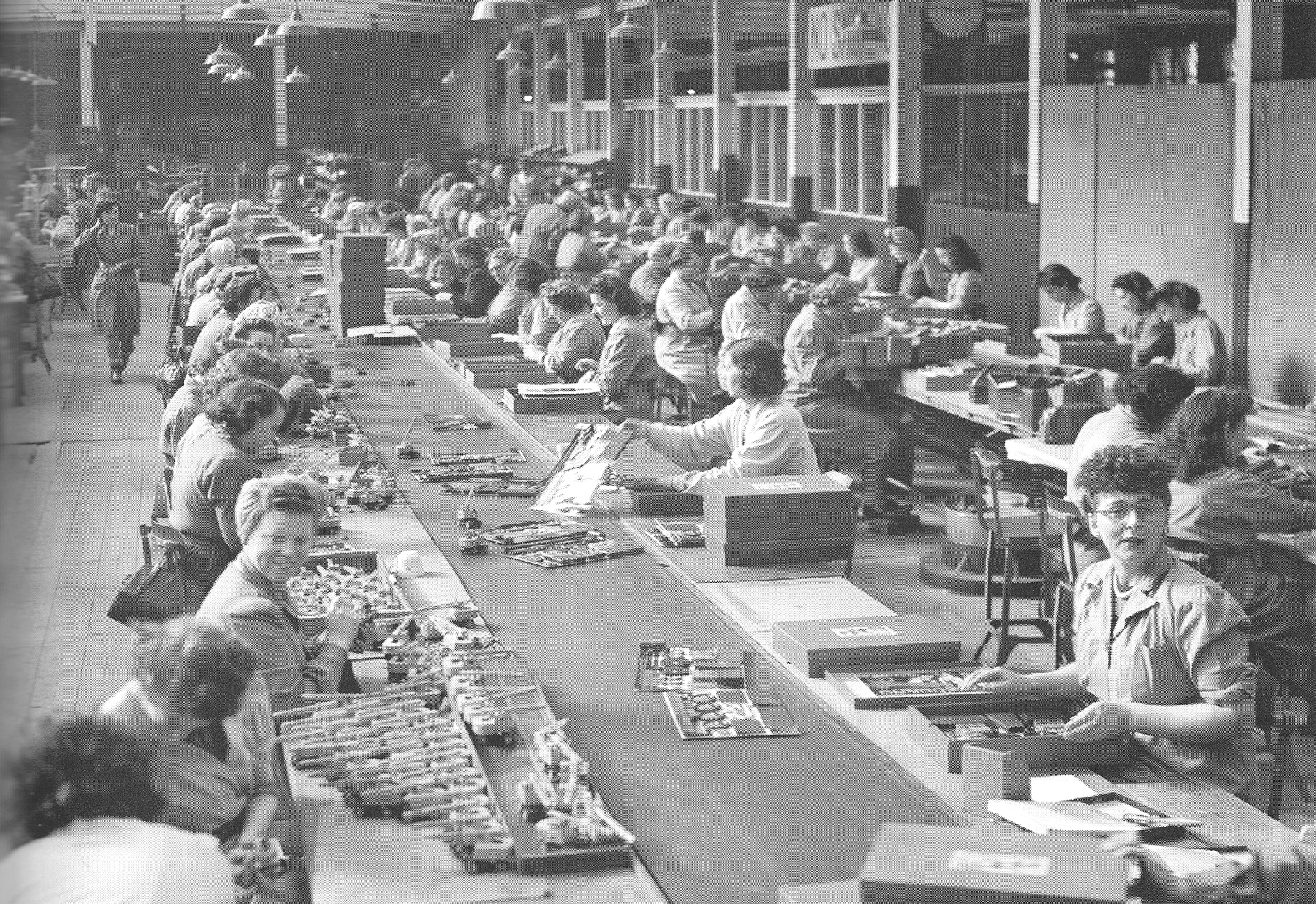
A typical assembly conveyor.
Image: Meccano Magazine
Output was fast, but the work was very repetitive and boring for the ladies so during the 1970’s a different approach was adopted in which a single lady had her own workstation supplied with all parts where she could build a complete product. For some products the conveyor system would still have to be used.
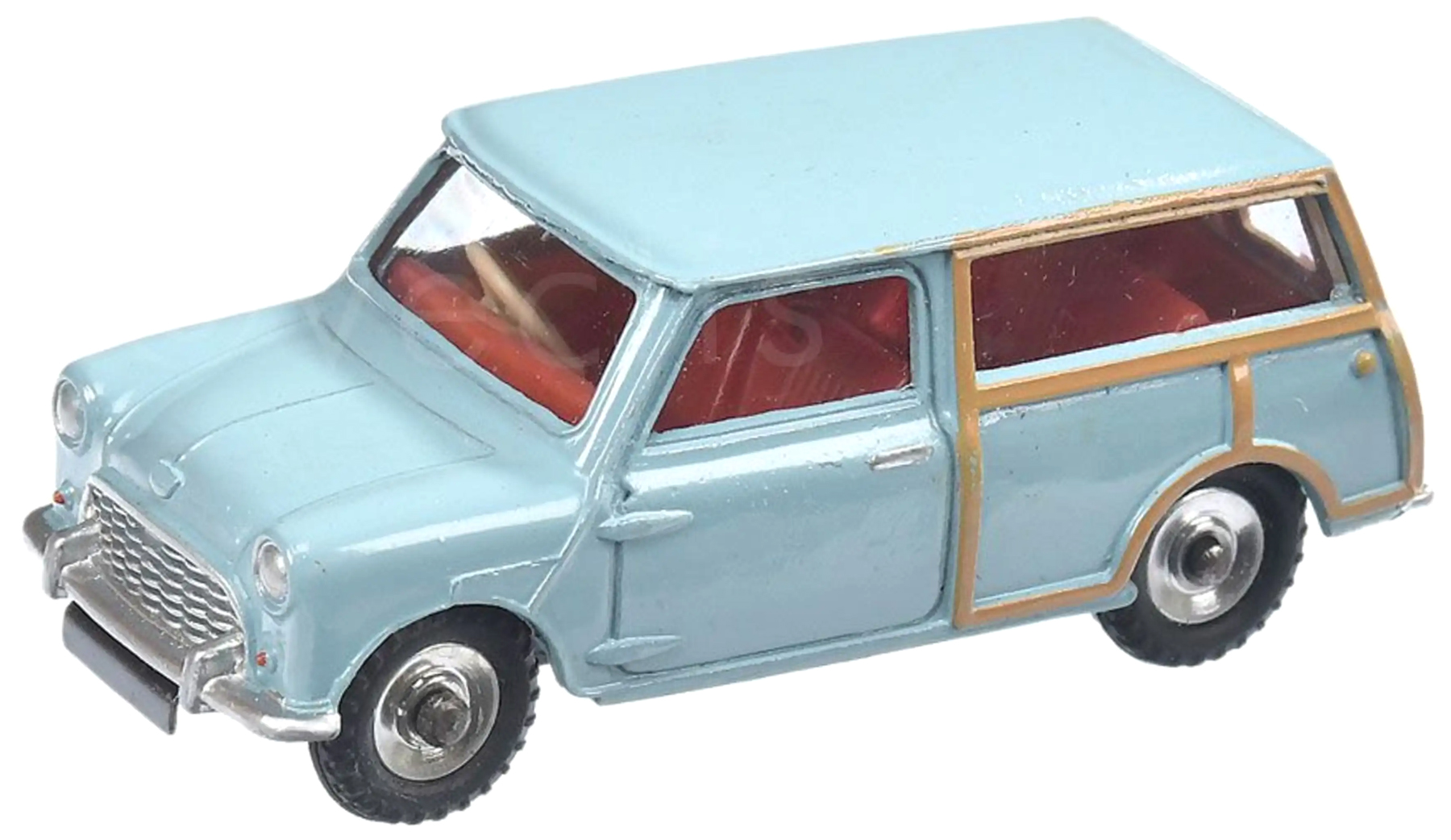
A completed Dinky 199 Austin Seven Countryman.
Image: Vectis Auctions
Modernizing the machinery
An important fact relates to the quality of diecast and plastic tooling. With the exception of press tooling (Dinky tin bases, Meccano etc.) prior to late 1962 all diecast and plastic tools weren’t hardened (heat treated) and quality “Hot Work” steels weren’t used.
Not using “Hot Work” steels reduced die life and in the extreme case where aluminum (which has nearly twice the melt temperature than Mazak) was used on the Vulcan Bomber, the die catastrophically failed after about 500 shots. So special new steels were used and tools hardened. This gave a tool life of potentially 250,000 shots using Mazak, depending on die complexity.
From 1961 and up to 1965, new high pressure fully automatic diecasting machines were gradually introduced with many ready for when the Speke casting facility was closed and brought into Binns Road. Because the original manually operated “Kipp” casters were no longer required they were phased out. This effectively gradually killed off dozens of Dinkys because the Kipp tooling wasn’t compatible with the new machines.
The new machines offered faster production and much denser quality castings with big savings on Mazak, because the path from injection point to cavity was much shorter and smaller. The machines were designed by a very clever gentleman Desmond Youde who was Senior Plant Engineer for Meccano, and were constructed at Binns Road.
The impact of metrication
During the 1970’s several changes took place, notably metrication (which Meccano took very seriously) which revised the general wall thickness for castings and moldings from 0.040″ to 1 mm. In the late 1970’s, wall thickness for castings was further reduced to 0.8 mm to save material and cost without any noticeable reduction in strength. Because the most used materials were Mazak and High Impact Polystyrene (HIP), the use of shrinkage allowance in tooling was abandoned as both these materials shrank at identical rates (0.6%).
With the average Dinky saloon being about 105 mm long, this introduced an overall scale length error of about 0.6 mm which wasn’t worth worrying about compared to the advantages of eliminating downstream errors when applying shrinkage. A further move was to draw designs on plastic film rather than traditional tracing paper. This eliminated the need to trace designs onto linen for durability as plastic film is virtually indestructible.
How it’s done today
Today of course, design and tooling are done very differently. Prototypes can be 3D laser scanned and the data loaded into a 3D CAD system for detailed design of the product. This 3D data can be used in stereolithography (desk top printing) to produce resin models for assessment, downloaded into CNC machines to directly machine detail into hardened steel, or to manufacture electrodes used in EDM (spark erosion) machines.
- CAD — Computer aided design
- CNC — Computer numerical machining
- EDM — Electric discharge machining
About the author
Vic Mumby joined Meccano Ltd. in 1961 as an apprentice toolmaker and transferred to the drawing office in 1965. After spending several years in product design, he transferred to tool design and finally became Chief Draughtsman from 1975 until the closure of the company in 1979.
Vic is active in the Hornby Railway Collectors Association (HRCA) and Dinky Toy Collectors Association (DTCA) and was interviewed by Jon Angel. You can read the interview here: