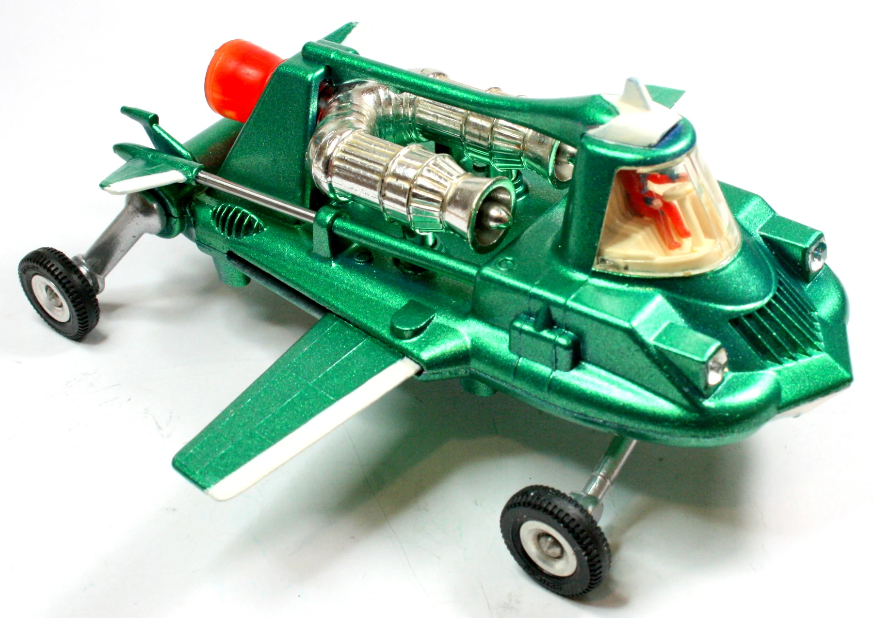
From 1965 to 1970, I worked on product design in Meccano’s drawing office. Sometime during 1968 I was tasked with designing Joe’s Car. The original proposed layout of this model was given to senior designer Terry Boland who only got as far as fixing the shape and layout of the major body parts when he was promoted to New Products Manager; so it was passed to me.
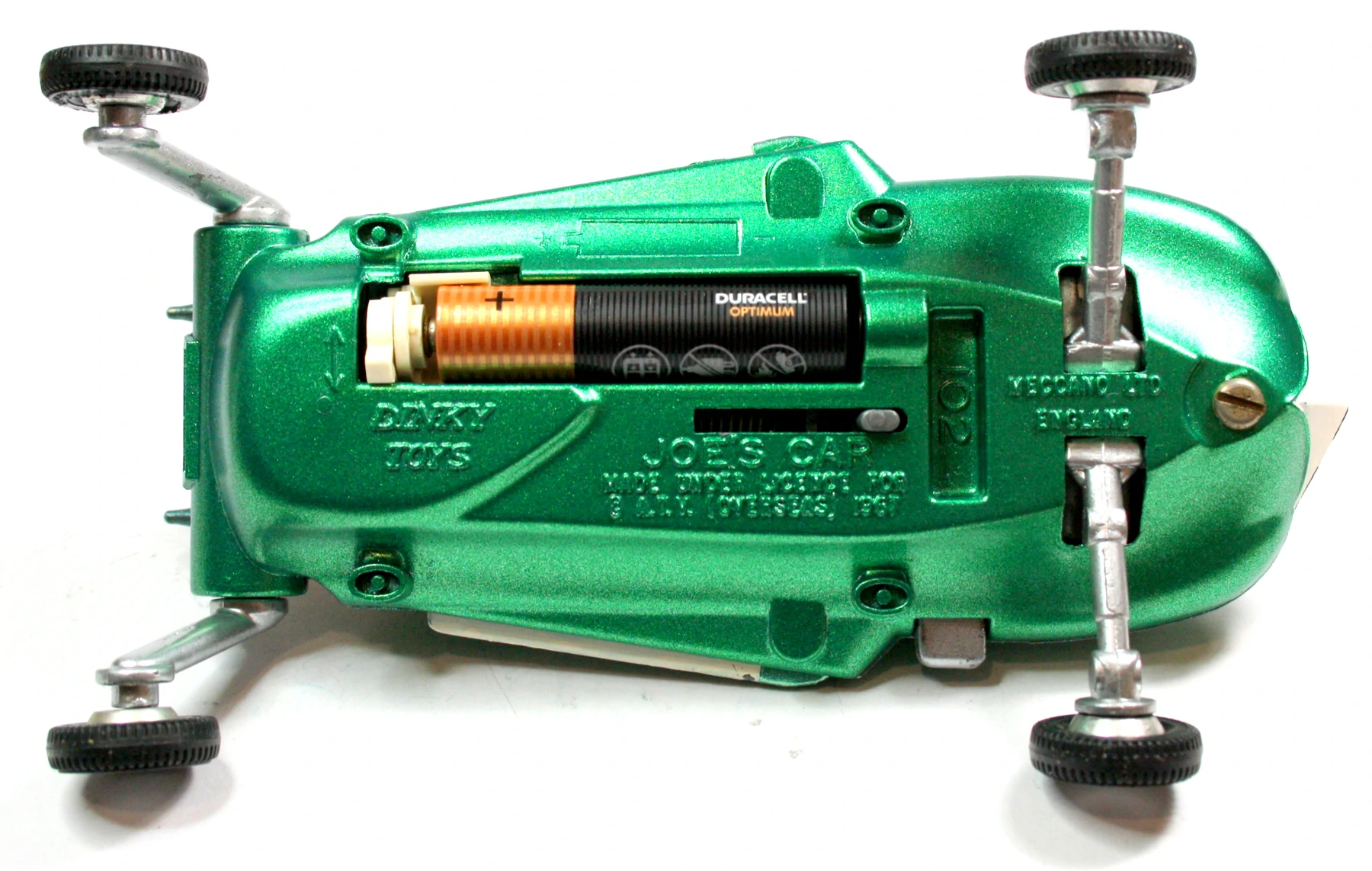
After about ten weeks of detail design and just before release for tooling, Managing Director Joe Fallman insisted on a flashing light within the engine cowl; so I had to shoe horn a AAA battery, switch and bulb holder into a chassis already already filled with mechanisms. In order to achieve this in a short timeframe, I was assisted by the late Fred Risk who was responsible for checking all product designs before handing them over to tool design. After working on numerous sketches a design was roughed out, so I committed it to paper. With no time left for making a mock up, it had to work right the first time.
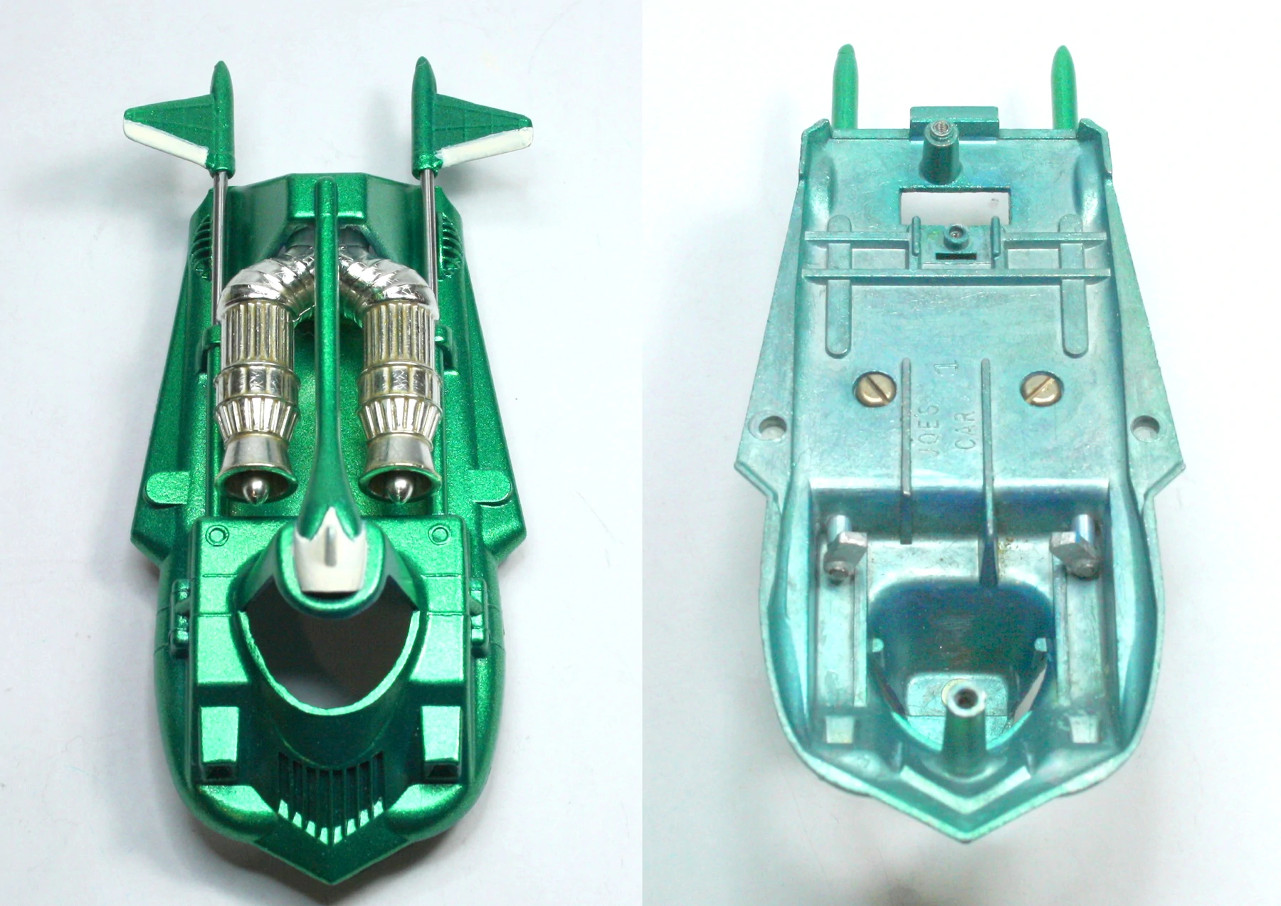
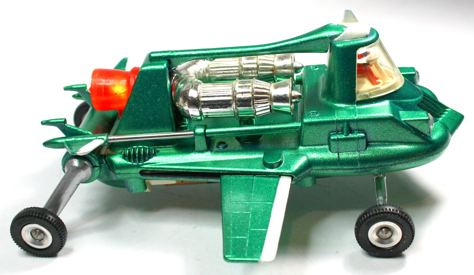
For the purposes of this article I have almost completely dismantled a rather shabby issue 1 Joe’s Car that was missing tail fins, piston rods and lugs. I managed to source white metal replacements for the fins and lugs, as well as a 2.2 mm diameter stainless steel rod for the pistons. I believe it is part of the 500 test pre-production run that every new Dinky undertook.
If all went well, the 500 finished and boxed models were put into storage for selling in the normal way, but an error was missed; the On/Off engraving for the switch had been left off and had to be corrected before serious production commenced. So the initial 500 boxed models must have been sold with the omission because they still keep turning up.
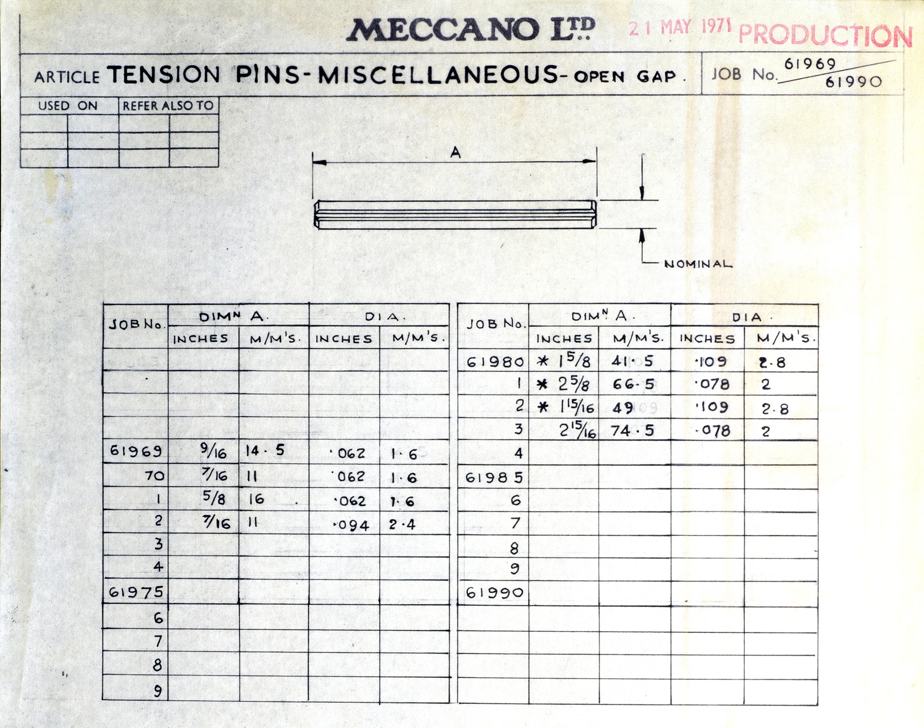
Tension pins list
Image: HRCA archive
In production, tension pins were used for the piston rods. Tension pins have a body diameter which is about 0.2 mm larger than the hole they’re meant to fit, and a chamfer on either or both ends to facilitate starting the pin into the hole. The spring action of the pin allows it to compress as it assumes the diameter of the hole. Job No. 61983, 74.5 mm is for Joe’s Car.
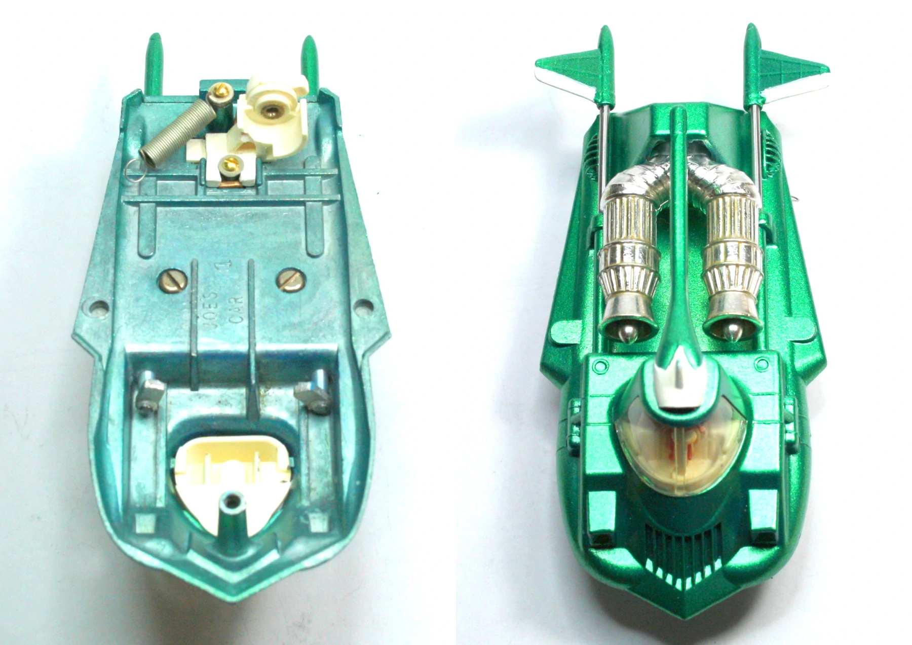
Dismantling
It was necessary to grind off the spun over rivet heads holding many of the parts together. To allow later reassembly, the remaining mazak spigots were drilled and tapped to accept 9BA round head screws and washers. No attempt was made to dismantle the glued seat assembly comprising seat, steering wheel and pilot, split the engine moldings apart, remove the semi-tubular rivet holding the switch to the lamp holder, or force fit the aluminum cylinders into the upper body. This was to avoid irreparable damage to these parts. The conical spring in the battery compartment was also left in place, being very securely staked in position. The paint I have used isn’t a true copy. This was not an issue for me as I wasn’t trying to create a perfect replica. The total number of parts is 59 which is very high for a Dinky Toy.
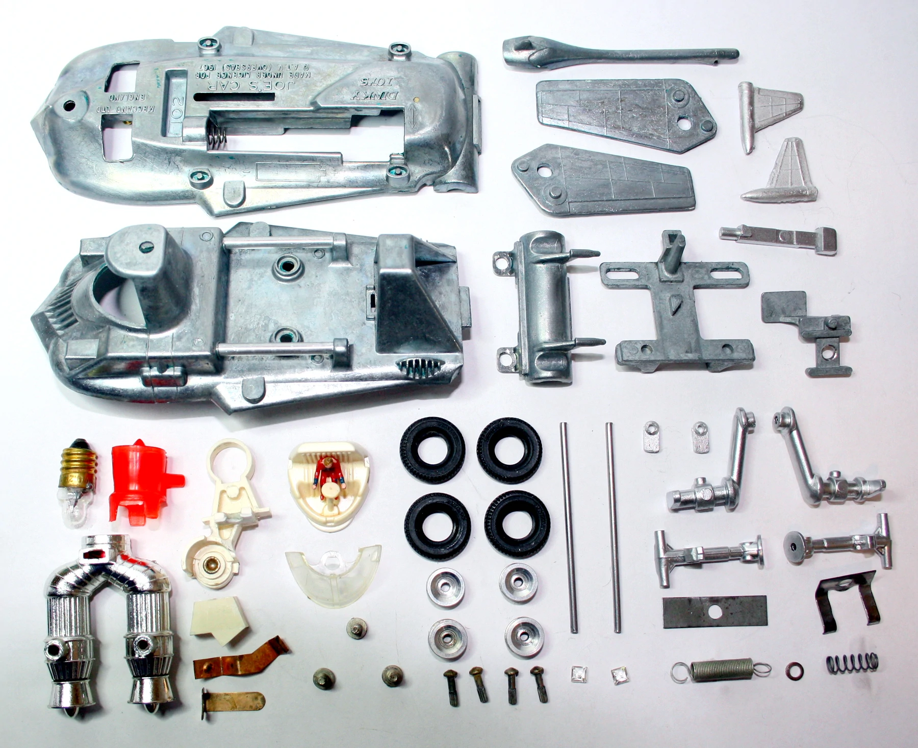
A full set of parts for Joe’s Car
Assembly
Obviously, all the assembly actions that follow would be aided in production by jigs and fixtures to locate parts correctly and prevent them from moving during riveting or screwing together.
I’ve attempted to sequence the build in the manner of production. The first action is to fit the aluminum cylinders and the top finned cross bar to the upper body. Next, all the parts finished in green would be auto sprayed and the white details masked sprayed by hand. Elsewhere, the mazak suspension arms would be zinc plated and the engine moldings ultrasonically welded together before being sent away for vacuum plating.
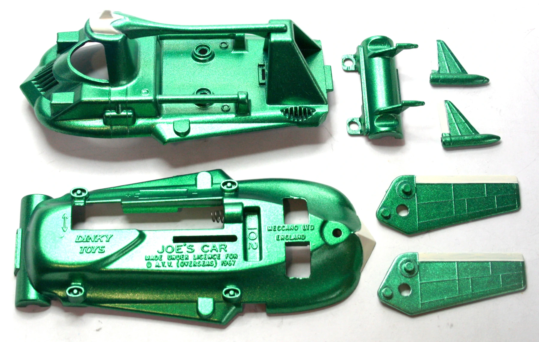
Painting completed
Now it’s time to create a number of sub-assemblies. The piston rods are pushed into the tail fins. The wheels are attached to the four suspension arms. The bulb carrier is fitted with the switch which comprises the switch lever and molded washer all secured with a semi-tubular rivet. The positive contact is then held in place by a molded clip. Finally, the pilot and his steering wheel are glued into the seat molding.
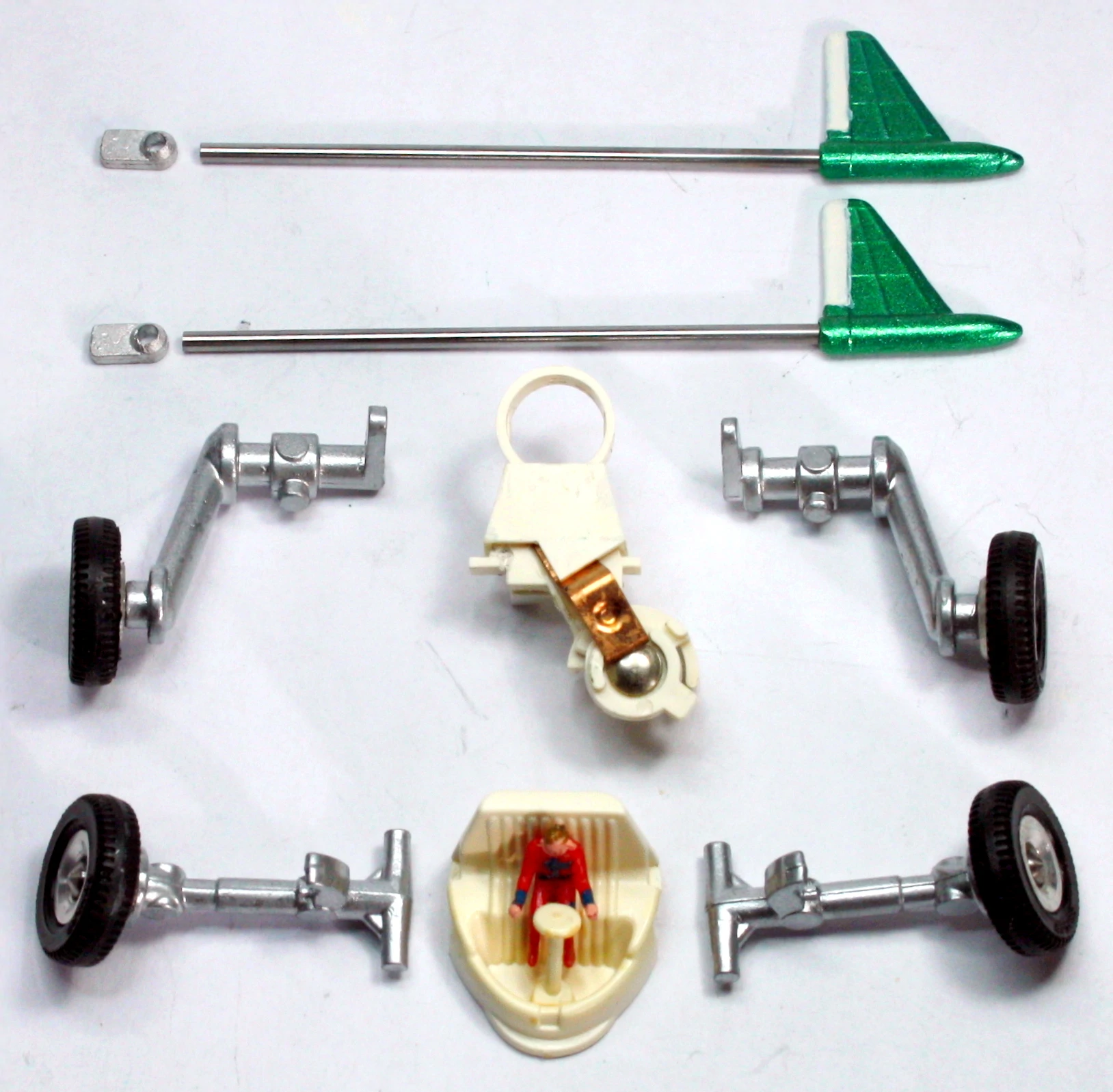
Subassemblies
Assembling the upper body
With the upper body held in a special fixture to ensure correct orientation with the lugs, the fins are fitted. The engine is now fitted and secured with two self tapping screws because the negative bulb contact passes through it at a later stage.
Fins, lugs and engine assembled
With the upper body still inverted, the extension spring and washer are attached to the tower at the rear of the body. Next, the bulb holder assembly is attached to the upper body, trapping the negative contact. Because it was impossible to hold the seat in place using supports cast into the lower body, the seat was dropped into the cab from below and held while the body was turned over and the window pushed into position. Clips molded on the interior of the window engage the seat, and a hole at the top of the window clips over a ramped stud cast into the roof of the cockpit, thus securing the window perfectly flush with the body. This completes assembly of the upper body.
Tension spring, seat and window fitted
Assembling the lower body
The rear suspension spring is secured, suspension arms located and held in place by the rear suspension cover which slots in and is secured with two spun over rivets. A compression spring is fitted to the wing release button which is then placed in the lower body, followed by the front suspension arms, suspension spring and release button retainer which holds everything in place. The conical battery spring is staked into position. The lower body assembly is now complete.
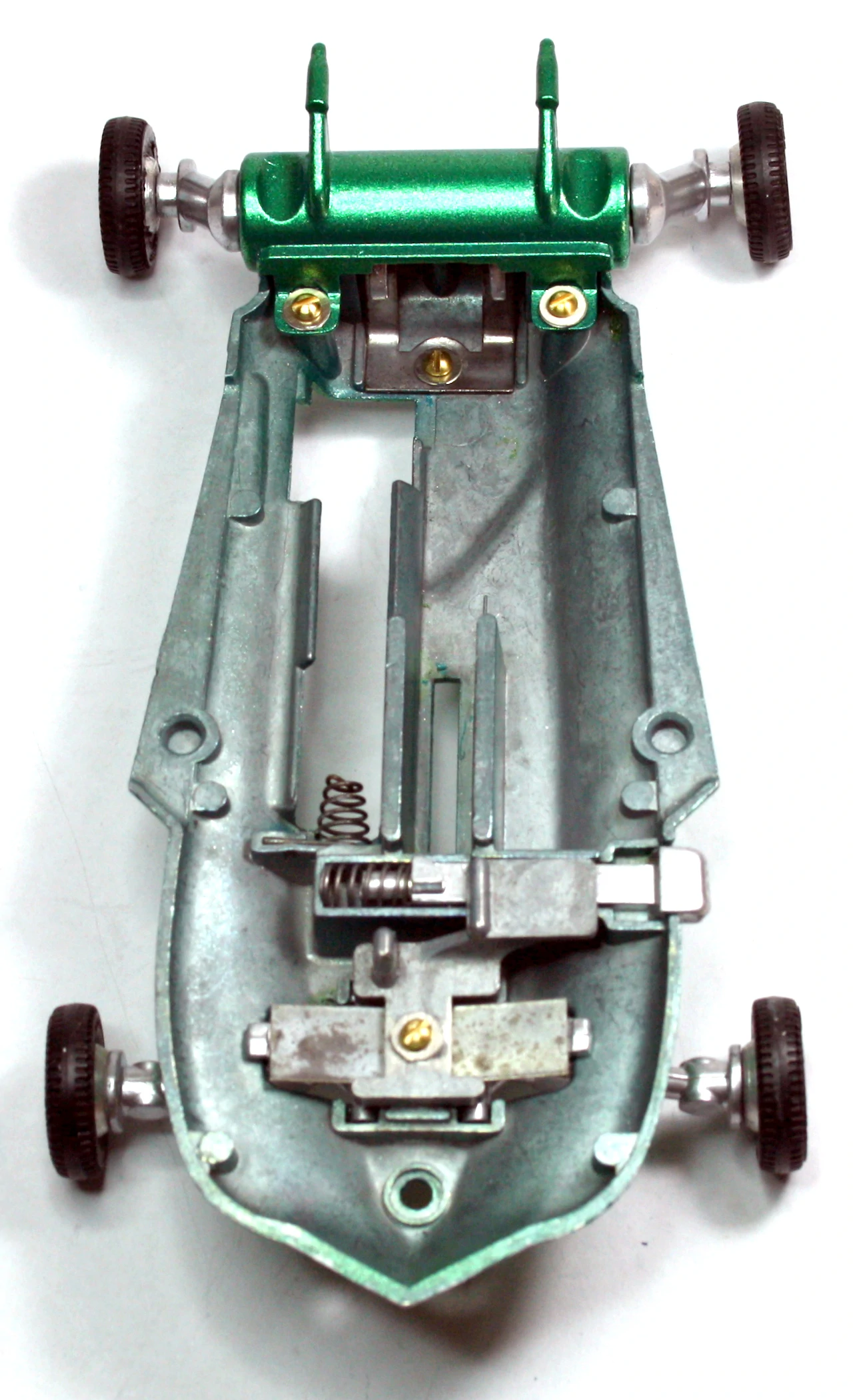
Lower body assembly
Final assembly
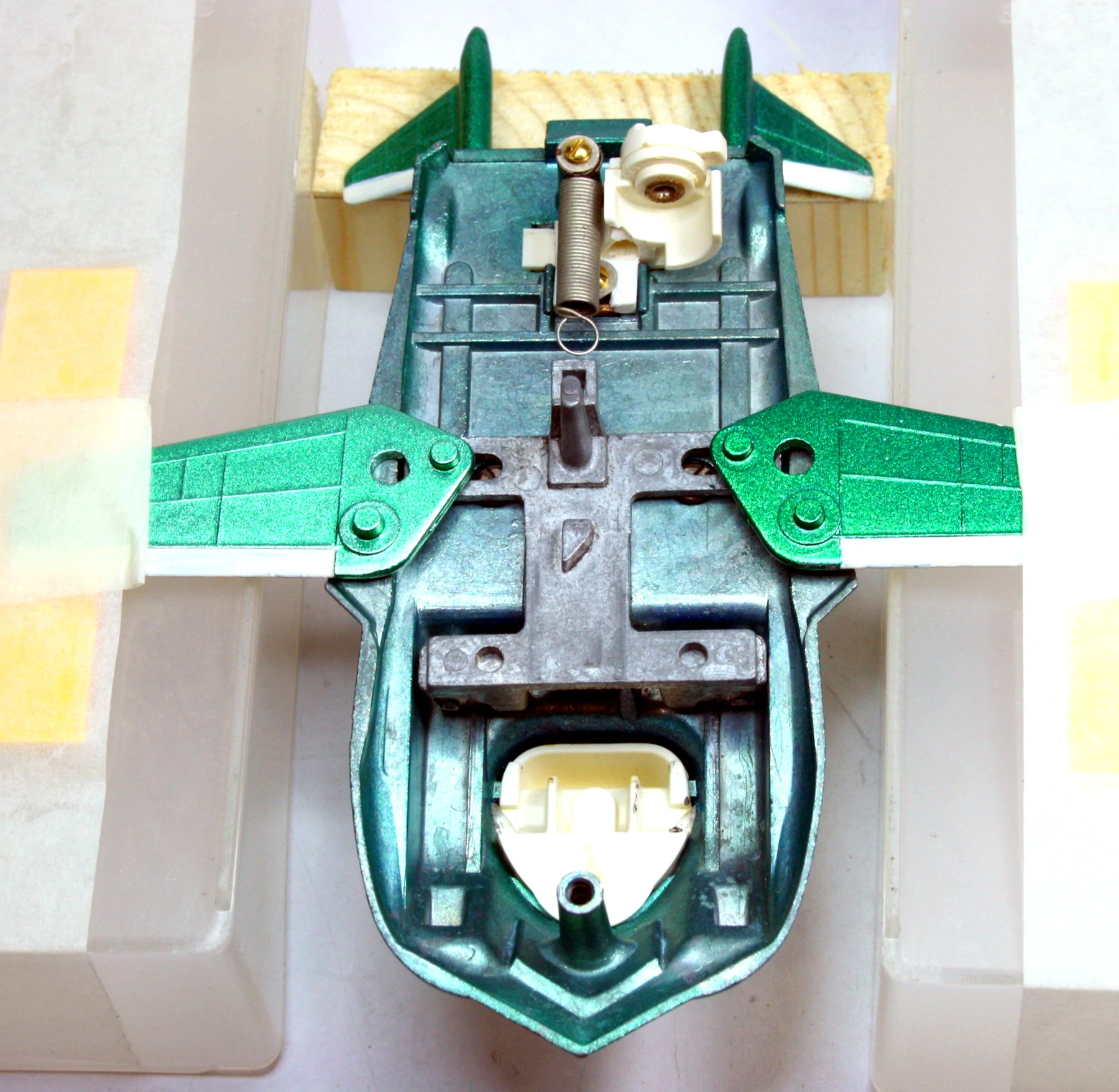
Now, the upper and lower bodies must be joined. With the lower body securely held in a special fixture, the wing actuator is placed in the body in the rear position ensuring that the tail fin lugs engage the slots in the actuator. Both wings are located in their pivot holes in the body, and the actuator is set to the open position and securely held down with clamps. The tension spring is hooked on to the actuator.
Lower body assembly
The upper body is now carefully hooked into the rear suspension cover and lowered into position. With a little jiggling, the wing pivots will find their holes in the upper body. Finally, the jeweled headlights are glued in, the bulb screwed into its holder and the engine exhaust fitted.
Final assembly
About the author
Vic Mumby joined Meccano Ltd. in 1961 as an apprentice toolmaker and transferred to the drawing office in 1965. After spending several years in product design, he transferred to tool design and finally became Chief Draughtsman from 1975 until the closure of the company in 1979.
Vic is active in the Hornby Railway Collectors Association (HRCA) and Dinky Toy Collectors Association (DTCA) and was interviewed by Jon Angel. You can read the interview here: